Hey everyone, if you’re working with substation transformers—whether you’re a utility engineer, maintenance lead, or someone who’s been burnt by unexpected energy costs—you know load loss is one of those sneaky, constant costs that add up way faster than you think. Last quarter, I had a utility client reach out saying their 10MVA transformer was running 12% over their monthly energy budget, and half of that was straight load loss. It made me realize a lot of folks don’t just know how to measure it properly—they’re guessing, which leads to overpaying or even safety issues. As a substation transformer supplier, we don’t just sell units; we make sure you get the most out of them, so today I’m breaking down how to measure load loss like a pro, no fancy (or confusing) jargon required. Substation Transformer
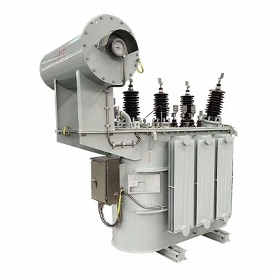
First, let’s get on the same page about what load loss actually is, because if you mix it up with no-load loss, you’re gonna get the wrong numbers quick. No-load loss is the energy your transformer uses just sitting there, plugged in, no load on it—think of it like a standby phone charger. Load loss, though? That’s the heat and energy lost when current flows through the transformer’s windings, plus some small losses from core and structural parts when there’s load on it. It’s proportional to the square of the load current, so when you’re running at full capacity, it’s way bigger than no-load loss. For example, a 25MVA transformer might have ~80kW no-load loss, but ~250kW load loss at full load. That’s 170kW you’re throwing away if you don’t have a handle on it.
Now, the big question: how do you actually measure this? There are two main ways we use at our shop and recommend to clients—direct load testing and no-load loss plus stray loss calculation. Wait, I know some people swear by only direct testing, but hear me out. Direct testing is the most accurate, but sometimes you can’t get a full load on the transformer (like if it’s already installed in a substation and can’t be taken offline easily). So we cover both, depending on your situation.
Let’s start with the direct load test, because that’s the gold standard for new transformers and when you can test before commissioning. Here’s how we do it step by step, no skipped steps: First, you need the right gear. Don’t use a $50 multimeter from the hardware store—you need calibrated equipment, otherwise your numbers are useless. We use a 3-phase power analyzer (like Fluke 438 or Power Quality Analyzer), current transformers (CTs) rated for at least 120% of the transformer’s full load current (FLC), and voltage probes that match the substation’s line voltage. The key here is calibration—your analyzer needs to be calibrated in the last 12 months, because even a 0.5% error will add up when you’re measuring hundreds of kW.
Next, set up the test correctly. First, de-energize the transformer, make sure it’s locked out and tagged out (safety first, always—no exceptions). Disconnect the secondary side load, then connect the power source to the primary side at rated voltage. Wait, no—wait, for a direct load test, you actually apply a controlled load to the secondary. Wait, I should clarify: for factory testing, we use a variable resistive load bank. For in-situ testing, if you can’t disconnect the load, you test under actual operating load, but that means you have to wait for different load levels, which is less accurate. Let’s split factory vs in-situ because that’s a common confusion.
Factory direct load testing (this is what we do for every unit we ship, by the way): Once the transformer is on our test pad, we connect a calibrated AC power supply to the primary, a resistive load bank to the secondary. The load bank is set to draw a specific percentage of the transformer’s rated load—25%, 50%, 75%, 100%, and sometimes 110% to check for overloading losses. We let the transformer run for 30 minutes at each load point to let it stabilize (so the heat doesn’t skew the readings), then record three things: primary voltage (Vp), primary current (Ip), secondary voltage (Vs), secondary current (Is), and the total real power drawn from the primary (P_total). Now, no-load loss (P0) is the power we measured when there was zero load on the secondary, right? So load loss (P_load) is just P_total minus P0. That’s it for factory testing—super accurate, because you control the load perfectly. Most manufacturers give a load loss number at 100% rated load, but we always share the full load curve with clients so you can see losses at any load, which is way more useful for your operations.
Now, in-situ direct load testing—this is when the transformer is already installed, online, and you can’t take it offline for a load bank test. How does that work? First, get your calibrated power analyzer, clamp your CTs around all three primary lines, and connect voltage probes to the primary bus. Wait, but you also need the secondary current, right? Because load loss depends on current. Oh, right—you can clamp CTs around the secondary lines too, or use the existing substation’s CT readings if they’re calibrated (most modern substations have this). Then, record data at 1-minute intervals for 24 hours (or longer, if load varies a lot) so you get data from light load, medium load, and peak load. Calculate the average load loss using the formula: P_load = (P_primary – P0) where P0 is the no-load loss you either get from the nameplate or measure when the transformer was offline. Wait, but here’s the catch: if the transformer is running at less than full load, the load loss is proportional to the square of the actual load current divided by rated current. So if your transformer is rated 100A secondary, and you’re running 50A, load loss is (50/100) squared = 0.25 times the full load loss. That’s why the 24-hour data is important—most transformers only run at full load a few hours a day, so average load loss is way lower than full load loss, which is what nameplates usually show.
Now, the second method: calculation-based, when you can’t do a direct load test at all. This is what we use for older transformers that have been in service for 20+ years, where you can’t get a load bank or don’t want to take readings during operation. The formula here is simple (I promise, no calculus): Total load loss = I² * R, where I is the actual load current, and R is the equivalent AC resistance of the windings. Wait, but AC resistance is different from DC resistance, right? Because of skin effect and proximity effect in the windings. So you can’t just use a DC resistance meter—you need to calculate AC resistance, or get the stray loss value from the transformer’s design data. For new transformers, the nameplate might have “load loss at rated current” which is the total winding loss plus stray loss (losses from structural parts). For older units, you can calculate AC resistance by measuring DC resistance at operating temperature, then adjusting for AC effects. Wait, let’s make that concrete: if you measure DC resistance of the primary winding at 25°C is 0.01 ohms, you adjust it to 75°C (standard operating temp) by multiplying by (75 + 235)/(25 + 235) = 1.192, so 0.01 * 1.192 = 0.01192 ohms. Then, multiply by the square of the current: if current is 100A, that’s 100² * 0.01192 = 119.2kW, then add stray loss (usually ~5-10% of winding loss) to get total load loss. This is less accurate than direct testing, but it’s a great backup when you can’t do anything else.
Wait, let’s talk about common mistakes people make when measuring load loss, because these are the things that mess up your numbers and your budget. First: forgetting to calibrate your equipment. Last year, a client brought us their test results and said their load loss was 30% higher than our factory number—turns out their CTs were 5 years past calibration, so their current readings were off by 15%. Second: not letting the transformer stabilize during testing. If you run a load test for 5 minutes, the windings haven’t heated up yet, so resistance is lower, leading to lower load loss readings than actual. We always wait 30 minutes, no exceptions. Third: mixing up primary and secondary power. A lot of people try to calculate load loss from secondary power, but secondary power is less than primary power because of losses—you have to use the total power drawn from the primary side to get the correct load loss. Fourth: only testing at full load. If your utility runs at 40% average load, the full load loss number on the nameplate is useless—you need average load loss, which comes from multiple load points.
Now, why does this matter for you? Let’s do a quick example. You have a 10MVA transformer, full load loss 250kW, no-load loss 80kW. Your average load is 40% of rated, so average load loss is 250 * (0.4)² = 40kW, plus 80kW no-load, total loss 120kW. If you pay $0.12 per kWh, that’s 120kW * 24h * 365d * $0.12 = ~$126,000 a year in losses. If you measured that wrong and thought it was $90,000, that’s $36,000 down the drain. And as your transformer supplier, we’ve seen this all the time—clients who didn’t measure load loss properly end up upgrading their transformer unnecessarily, or keep an inefficient unit too long because they don’t realize how much they’re wasting.
Wait, also, for new transformers, we always provide the type test report with load loss data, so you don’t have to measure it yourself before commissioning. But if you want to verify it post-install, we can walk you through the test steps, or send a technician to do it for you—we offer on-site testing as part of our post-install support, because we want our clients to get exactly what they paid for.
Now, let’s wrap this up so it’s actionable, not just theory. Here’s your step-by-step cheat sheet for measuring substation transformer load loss:
- Confirm if you can do a direct test (new unit, offline) or need in-situ/calculation method.
- Use only calibrated equipment—no exceptions. Calibration expires every 12 months, so check that sticker on your power analyzer and CTs.
- For direct factory testing: Test at 25, 50, 75, 100% load, wait 30 mins per point, subtract no-load loss from total primary power to get load loss.
- For in-situ testing: Record data every 1 min for 24+ hours, calculate load at each point, use the I²R formula for load loss, average across the day.
- For older units without direct test access: Measure DC resistance, adjust to operating temp, add stray loss (5-10% of winding loss) to get approximate load loss.
If this sounds like a lot, or if you’re measuring load loss and your numbers don’t line up with your transformer’s nameplate, reach out. As a substation transformer supplier, we don’t just sell units—we help you keep operating costs low, avoid unexpected energy bills, and make sure your equipment is working safely and efficiently. Whether you need a technician to run on-site load testing, want to verify your current transformer’s performance, or are looking to upgrade to a more efficient unit with guaranteed load loss, we’re here to help you work through it.

Don’t guess at load loss—get accurate numbers, save money, and keep your substation running smoothly. Hit us up to chat through your specific setup, no pressure, just real advice from people who work with transformers every day.
GIS On-line Monitoring System References
- IEEE Std C57.12.90, Standard Test Code for Liquid-Immersed Distribution, Power, and Regulating Transformers
- IEC 60076-1, Power Transformers – Part 1: General
- NEMA TP 1-2002, Energy Management Guide for Distribution Transformers
Baoding Shangwei Electric Technology Co., Ltd.
We are one of the most professional substation transformer manufacturers and suppliers in China, also support customized service. We warmly welcome you to buy durable substation transformer at competitive price from our factory. If you have any enquiry about quotation, please feel free to email us.
Address: Building 6, Baoding Zhongguancun Digital Economy Industrial Park, No. 777 Lixing Street, Baoding City, Hebei Province, China
E-mail: wendylu@swspower.com
WebSite: https://www.swspower.com/
